Showing all 3 results
Autologic Controls manufactures industrial thermowells in Ahmedabad, India, available in three standard mounting configurations: Flanged, Threaded (Screwed), and Weld-in. Our thermowells are machined from high-quality bar stock in SS304, SS316, SS316L, and Inconel 600, and are designed to protect temperature sensors, thermocouples, and RTD PT100 sensors from direct contact with harsh process media while allowing accurate temperature measurement.
What sets Autologic apart is that we manufacture both the thermowell and the sensor. This means you get matched assemblies thermowell bore size and insertion length precisely coordinated with your sensor sheath OD and tip from a single supplier, eliminating the fitment mismatch issues that often occur when thermowell and sensor are sourced separately. We supply across Gujarat and pan-India, with custom thermowell designs accepted for non-standard process conditions.
What Is a Thermowell and Why Is It Used?
A thermowell is a pressure-tight fitting permanently installed into a process pipe, vessel, tank, or duct wall. It is a closed-end tube typically machined from bar stock — into which a temperature sensor (thermocouple or RTD) is inserted from the open end outside the process. The closed end of the thermowell is immersed in the process fluid and transfers heat to the inserted sensor, enabling temperature measurement without the sensor making direct contact with the process medium.
The thermowell serves four critical functions in any industrial temperature measurement installation:
- Pressure sealing: The thermowell forms the pressure boundary between the process (which may be at high pressure) and the atmosphere. The sensor inside is at atmospheric pressure — it can be withdrawn and replaced without depressurizing the system.
- Sensor protection: Direct immersion of a sensor in a high-velocity, corrosive, abrasive, or high-pressure process would quickly destroy it. The thermowell absorbs all mechanical and chemical attack — it is replaceable at a lower cost than a precision sensor assembly.
- Sensor replaceability: Because the thermowell is permanently installed and sealed, the sensor inside can be removed for calibration, inspection, or replacement at any time without shutting down the process or draining the vessel.
- Contamination prevention: In food, pharmaceutical, and clean process applications, the thermowell prevents any material from the sensor (wiring insulation, solder, metal particles) from contaminating the process medium.
The trade-off is response time, a thermowell adds thermal mass between the process fluid and the sensor, slowing the response to temperature changes. Thermowell design (stem shape, wall thickness, material) is carefully selected to balance sensor protection with acceptable response speed.
Types of Thermowells We Manufacture
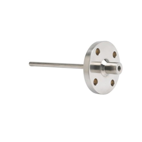
1. Flanged Thermowell
A flanged thermowell has a flange at the process connection end that bolts directly to a matching flange or thermowell nozzle on the pipe or vessel wall. This is the most robust mounting method and is used wherever high-pressure, high-temperature, or large-bore process connections demand a secure, leak-tight, and permanent installation.
Flanged thermowells are available with ANSI/ASME B16.5 flanges in ratings from 150# to 2500# and facing types including Raised Face (RF), Flat Face (FF), and Ring Type Joint (RTJ). The flange OD and bolt circle are matched to the standard pipe flange at the installation nozzle. Flanged thermowells are the standard choice for oil and gas pipelines, steam systems, high-pressure chemical reactors, and all installations requiring ASME pressure vessel compliance.
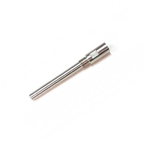
2. Threaded (Screwed) Thermowell
A threaded thermowell has an external thread (NPT or BSP) at the process end that screws into a matching threaded coupling, boss, or pipe fitting welded to the process pipe or vessel. This is the most common and cost-effective thermowell mounting for lower-pressure applications, and is widely used in industrial plants, HVAC systems, heat exchangers, and general process equipment.
Threaded thermowells are simpler to install than flanged types and do not require a mating flange. They are available in 1/2″ NPT, 3/4″ NPT, 1″ NPT, and BSP equivalents as standard, with other thread specifications on request. For applications above 300 psig, flanged or weld-in types are generally preferred for safety. Threaded thermowells are suitable for most general industrial temperature measurement requirements at moderate pressures and temperatures.
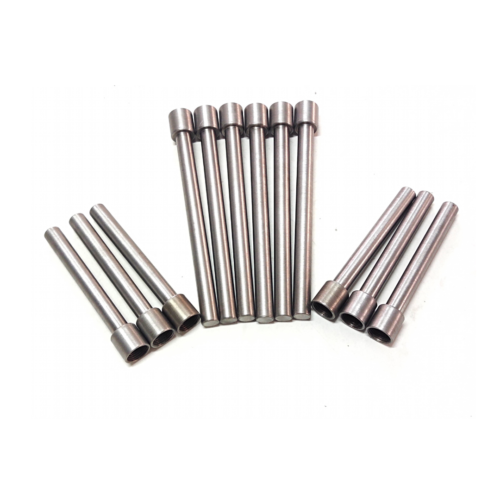
3. Weld-in (Socket Weld / Weld-neck) Thermowell
A weld-in thermowell is permanently welded into the process pipe or vessel nozzle — there is no removable threaded or flanged joint at the process connection. This eliminates all potential for thread leakage or flange gasket failure, making weld-in thermowells the choice for extremely high-pressure, high-temperature, or highly toxic process streams where even a minor leak at the process connection is unacceptable.
Weld-in thermowells are also used in sanitary and pharmaceutical applications in the socket-weld or Van Stone (lap joint) configuration, where the well can be removed from the piping flange for cleaning without breaking the weld seal. Once a weld-in thermowell is installed, it cannot be removed without cutting — so installation position and thermowell design must be finalized before welding.
Thermowell Stem Shapes – Straight, Stepped, and Tapered
The shape of the thermowell stem and the section immersed in the process significantly affect response time, vibration resistance, pressure drop, and mechanical strength. Three standard stem profiles are available:
| Stem Type | Profile | Key Advantage | Best For |
|---|---|---|---|
| Straight | Constant OD from root to tip — same diameter throughout insertion length | Simplest to manufacture. Maximum corrosion allowance at tip. Equal wall thickness throughout. | Low to moderate velocity, corrosive media where wall thickness at tip is important, general industrial use |
| Stepped | Larger OD at root, reduced OD at tip (typically 3/4″ reducing to 1/2″) | Faster response time at tip due to smaller thermal mass. Better flow characteristics than straight. | Moderate to high velocity processes. Where faster response is needed without full taper machining cost. |
| Tapered | Continuously reducing OD from root to tip — cone-shaped profile | Best vibration resistance and highest natural frequency. Fastest response. Lowest flow-induced stress. | High-velocity gas or liquid flows. Applications requiring ASMA PTC 19.3 wake frequency compliance. Oil & gas pipelines. |
Wake frequency calculations per ASME PTC 19.3 TW-2010 can be provided on request for critical high-velocity applications to confirm thermowell mechanical integrity.
Thermowell Technical Specifications
| Parameter | Available Specifications |
|---|---|
| Mounting Type | Flanged / Threaded (NPT or BSP) / Weld-in (socket weld, Van Stone) |
| Stem Shape | Straight / Stepped / Tapered |
| Material | SS304, SS316, SS316L, Inconel 600 (standard) | Carbon Steel A105, Hastelloy, Monel on request |
| Bore Diameter (U-bore) | Matched to sensor sheath OD — typically 6mm, 8mm, 10mm, 11mm bore |
| Insertion Length (U) | 50mm to 500mm+ — as per pipe/vessel immersion requirement |
| Lagging Extension (T) | Optional — for insulated pipes or vessels where additional standoff is needed |
| Flange Rating (Flanged Type) | ANSI/ASME 150# to 2500# | Facing: RF, FF, RTJ |
| Thread Size (Threaded Type) | 1/2″ NPT, 3/4″ NPT, 1″ NPT, BSP equivalents — other sizes on request |
| Pressure Rating | Depends on material, wall thickness, stem shape, and temperature — confirmed by calculation |
| Temperature Range | Up to 600°C (SS316) / up to 1100°C (Inconel 600) |
| Surface Finish | Machined (standard) | Electropolished (pharmaceutical/food grade on request) |
| Standards | ASME PTC 19.3 TW-2010 (design reference) / IS standards / IBR on request |
| Customization | Full — any insertion length, bore size, material, stem shape, connection size, lagging extension |
Thermowell Material Selection Guide
| Material | Max Temp. | Recommended Process Environment |
|---|---|---|
| SS304 | 900°C | General industrial fluids, water, steam, air, mild chemicals. Most cost-effective option for non-corrosive service. |
| SS316 / SS316L | 900°C | Chloride-containing environments, seawater, chemical processing, pharmaceutical manufacturing, food and beverage. Superior corrosion resistance vs SS304. |
| Inconel 600 | 1100°C | High-temperature oxidizing and carburizing atmospheres, furnace applications, heat treatment environments, and high-temperature steam. Standard for applications above 600°C. |
| Carbon Steel A105 | 425°C | High-pressure oil and gas service, steam at moderate temperatures. Low cost for non-corrosive hydrocarbon service. Requires external corrosion protection if moisture is present. |
| Hastelloy C276 | 1000°C | Severely corrosive media — strong acids (HCl, H2SO4), oxidizing chloride environments, wet flue gas. Specified when SS316 is insufficient. |
SS316 is the default recommended material for most industrial thermowell orders. Specify your process fluid, temperature, and pressure when requesting a quotation so we can confirm material suitability.
How to Select the Right Thermowell – Buyer’s Step-by-Step Guide
Step 1: Choose the Mounting Type
Select Flanged if the pipe or vessel already has a flanged nozzle, or if system pressure exceeds 300 psig, or if the installation is safety-critical (boilers, high-pressure steam, gas lines). Select Threaded if the installation is at moderate pressure (below 300 psig) and a threaded boss or coupling is present or easily added. Select Weld-in if process conditions are extreme (very high pressure, toxic media, cryogenic) or if a zero-leak installation is required and permanent fixing is acceptable.
Step 2: Define the Insertion Length (U dimension)
The insertion length is the distance from the process connection face to the tip of the thermowell — the length immersed in the process fluid. For pipes, the standard recommendation is to insert to the centre-line of the pipe or to at least 1/3 of the pipe internal diameter, whichever gives better flow contact. For tanks and vessels, the thermowell tip must reach the zone of interest — not just the nozzle connection. Measure and specify this dimension carefully: an insertion length that is too short will give inaccurate readings because the tip is not in the process fluid.
Step 3: Select the Stem Shape
For standard industrial applications at moderate flow velocities, a straight stem thermowell is adequate. For applications with higher fluid velocities or where faster temperature response is needed, specify a stepped or tapered stem. For high-velocity gas or liquid streams (above 1–2 m/s in liquids, above 10–15 m/s in gases), a wake frequency calculation per ASME PTC 19.3 TW should be performed to verify that vortex shedding will not cause resonance and mechanical failure of the thermowell. Contact us to arrange this calculation for critical installations.
Step 4: Match the Bore to Your Sensor
The internal bore (U-bore) of the thermowell must match the sheath OD of the sensor being inserted. A 6mm OD thermocouple or RTD requires a thermowell with a 6mm or 6.5mm bore. A loose fit creates an air gap that slows response; too tight a fit risks jamming the sensor or preventing removal. When ordering from Autologic Controls, we coordinate bore size with the sensor sheath OD — ensuring a matched fit from the same manufacturer.
Step 5: Specify Lagging Extension if Needed
If the pipe or vessel is insulated, add a lagging extension (T dimension) — the section between the process connection and the head or terminal block of the sensor that runs through the insulation. Without a sufficient lagging extension, the sensor head sits inside or adjacent to the insulation, trapping heat at the terminal connection and affecting cold-junction compensation accuracy in thermocouples or causing elevated ambient temperature errors in RTDs.
Matched Thermowell + Sensor from One Manufacturer – The Autologic Advantage
One of the most common installation problems in industrial temperature measurement is a mismatch between the thermowell bore and the sensor sheath OD, causing either excessive clearance (poor thermal contact, slow response) or inability to insert or remove the sensor (too tight). This happens when the thermowell and sensor are sourced from different suppliers with different machining tolerances.
Because Autologic Controls manufactures both thermowells and temperature sensors, RTD PT100 sensors, thermocouples (K, J, R, S, B, T types), and mineral insulated assemblies, we can supply matched thermowell + sensor assemblies confirmed to fit correctly, with the correct insertion length for your pipe specification, and with the sensor calibrated and tested against the thermowell assembly. This reduces installation issues and commissioning time on site.
Industries Where Thermowells Are Used
- Oil and Gas: Pipeline temperature measurement, separator vessels, heat exchangers — high-pressure flanged thermowells in Carbon Steel or SS316, often requiring wake frequency analysis.
- Power Plants and Boilers: Steam temperature measurement on superheaters, economizers, condensate lines — IBR-compliant flanged thermowells in SS316 or Alloy Steel.
- Chemical and Petrochemical: Reactor jackets, distillation columns, storage tanks — SS316 or Hastelloy, depending on process fluid corrosiveness.
- Pharmaceutical Manufacturing: Bioreactor vessels, autoclave sterilizers, WFI systems — SS316L electropolished thermowells with sanitary tri-clamp or flanged connections for GMP compliance.
- Food and Beverage: Pasteurizers, mixing tanks, CIP systems — hygienic SS316L thermowells with sanitary fittings and smooth bores to prevent bacterial harborage.
- HVAC and Building Services: Chilled water and hot water circuits, air handling unit coils, duct installations — threaded SS304 thermowells with standard 1/2″ NPT connections.
- Water and Wastewater Treatment: Effluent temperature measurement, digester tanks, aeration tanks — SS316 or lined thermowells for corrosive wastewater environments.
- Heat Treatment Furnaces: Salt bath temperature, annealing furnace atmosphere — Inconel 600 thermowells for high-temperature oxidizing atmospheres.
Frequently Asked Questions
What is a thermowell and what does it do?
A thermowell is a closed-end tube permanently installed in a process pipe, vessel, or tank that allows a temperature sensor to measure process temperature without directly contacting the process fluid. It forms the pressure boundary of the installation, protects the sensor from mechanical damage, chemical attack, and high flow velocities, and allows the sensor to be removed and replaced without shutting down or depressurizing the process. Heat conducts through the thermowell wall to the sensor tip, enabling accurate temperature measurement.
What are the different types of thermowells?
Thermowells are categorized by their process connection method. Threaded (screwed) thermowells have an NPT or BSP thread that screws into a pipe coupling the most common type for general industrial use at moderate pressures. Flanged thermowells bolt to a matching nozzle flange used in high-pressure and safety-critical applications. Weld-in thermowells are permanently welded into the process nozzle used where zero risk of thread or gasket leakage is required. They are also available in three stem shapes: straight, stepped, and tapered each offering different trade-offs between response time, vibration resistance, and corrosion allowance.
What is the difference between a straight, stepped, and tapered thermowell stem?
A straight stem has the same outer diameter from root to tip simplest to manufacture with maximum wall thickness for corrosion resistance, but most susceptible to flow-induced vibration. A stepped stem has a larger OD at the root reducing to a smaller OD at the tip reducing thermal mass for faster response while maintaining a robust root. A tapered stem continuously narrows from root to tip providing the best vibration resistance and fastest response time, but with less corrosion allowance at the tip. For high-velocity process streams, tapered thermowells are the engineering preference and are often required by ASME PTC 19.3 wake frequency analysis.
What is wake frequency calculation and when is it needed for a thermowell?
When fluid flows past a thermowell stem, it creates alternating vortices a phenomenon called vortex shedding. If the vortex frequency matches the thermowell's natural resonant frequency, mechanical resonance occurs and the thermowell can fail by fatigue fracture a potentially catastrophic event in a pressurized system. ASME PTC 19.3 TW-2010 is the standard calculation method to verify thermowell safety for a given combination of fluid velocity, density, pipe size, and stem shape. This calculation is required for fluid velocities typically exceeding 1 m/s in liquids or 10 m/s in gases common in oil and gas pipelines and steam lines.
How do I select the correct thermowell insertion length?
The insertion length (U dimension) is the distance from the process connection face to the thermowell tip. For pipe installations, the tip should reach at least the pipe centerline or a minimum of one-third of the pipe internal diameter to ensure full immersion in the flowing fluid. For vessels and tanks, the insertion length is determined by the depth of the measurement zone. Always specify the pipe internal diameter, nozzle standout height, and any insulation thickness when ordering, so the correct U dimension can be confirmed. A thermowell tip that does not reach the process fluid gives inaccurate readings.